ASICMiner Tube Setup Guide
|
Contents
0a) Introduction 0b) What You Need 0c) Parts List 0d) Tools Required 1) Assembly 2) Powering 3) Cooling 4) Case 5a) Configuration 5b) Configuration - Using Proxy (Optional) 6) Troubleshooting 7) Where to buy |
|
0) Introduction
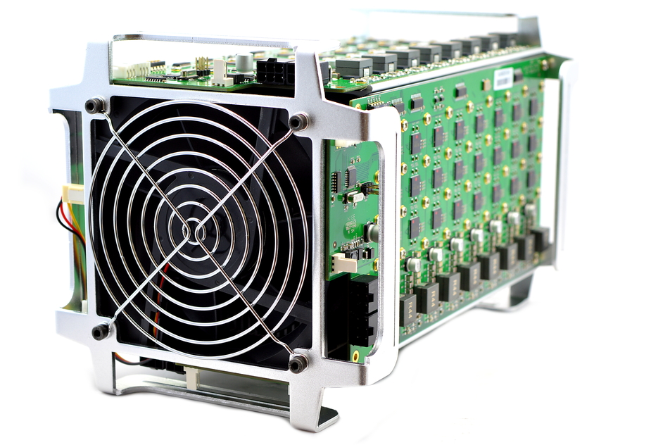
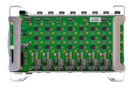
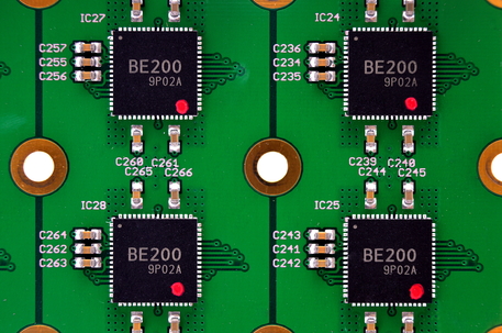
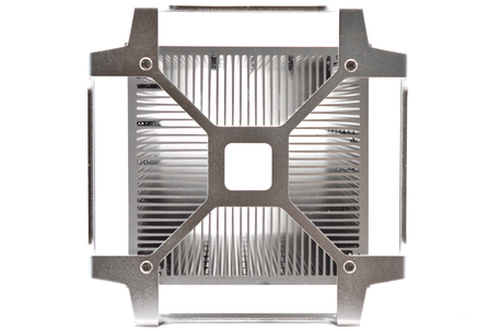
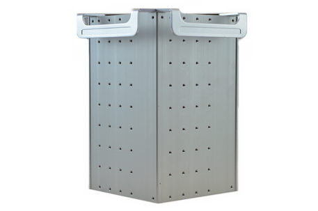
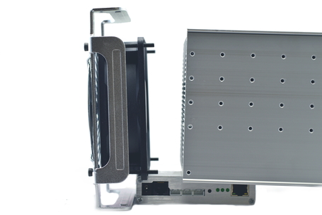
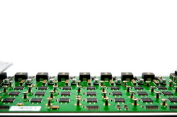
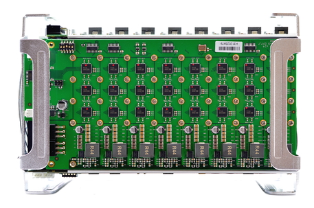
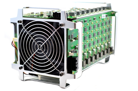
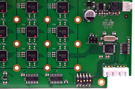
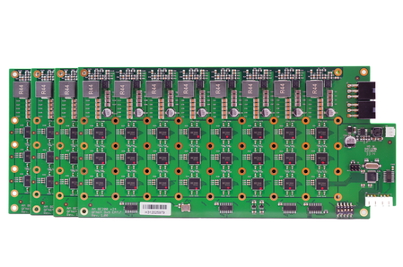
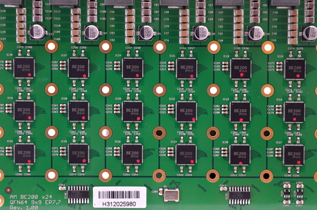
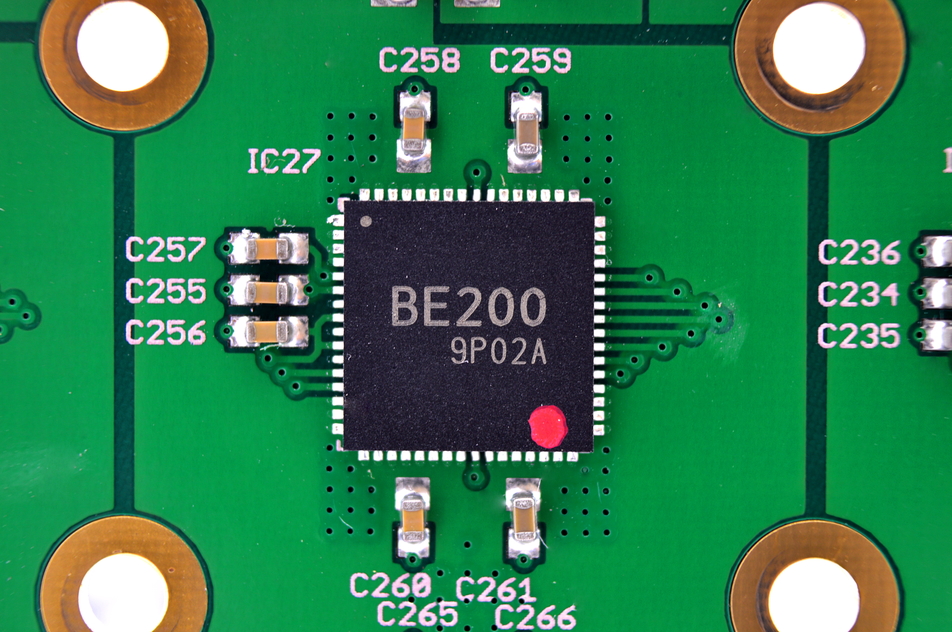
ASICMiner's Tube is the official release of their open sourced x24 reference design and their first consumer product release in 9 months. It features 4 hashing boards, each featuring 24 BE200 generation 3 chips arranged around a central aluminium core heatsink. Lightweight stands at each end allow the units to be stacked and 8 miners can be daisy chained to one controller. Tubes can be purchased preassembled or as kits.
ASICMiner's Tube is the official release of their open sourced x24 reference design and their first consumer product release in 9 months. It features 4 hashing boards, each featuring 24 BE200 generation 3 chips arranged around a central aluminium core heatsink. Lightweight stands at each end allow the units to be stacked and 8 miners can be daisy chained to one controller. Tubes can be purchased preassembled or as kits.
|
Chips
Rated Hash Rate Rated Voltage Rated Current Power Consumption |
- 96x ASICMiner Gen3
- ~830GH, 920GH (OC) - 12V - 75A, 85A (OC) - ~900W, 1025W (OC) |
0b) What You Need
You will need a few accessories and a power supply to get started.
You will need a few accessories and a power supply to get started.
Click your flag to find everything you need to get started at Amazon!
0c) Parts List
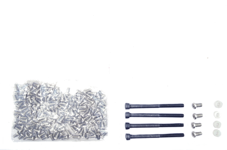
Each unassembled ASICMiner Tube kit will contain the following parts. Please check you have all the components before getting started.
Each unassembled ASICMiner Tube kit will contain the following parts. Please check you have all the components before getting started.
0d) Tools Required
With 164 screws to assemble each Tube, using the right screwdriver will save you significant time. Everything can be done with a 3.0mm slotted screwdriver, but its very important that the handle and blade is thin otherwise you won't be able to access some of the screw holes. You will need this regardless of whether you choose to get a handheld electric screwdriver as well.
It is recommended to get a light, handheld electric screwdriver as the time savings will pay for themselves and you'll also have a useful tool for the house. Don't bother using a normal large drill as they're too cumbersome and you risk damaging the miner. Whichever one you chose, make sure it has variable torque otherwise you'll strip screw heads. Some suitable recommendations are included below, as well as the correct manual screwdriver.
Click your flag to find everything you need to get started at Amazon!
1) Assembly
Those who purchased their Tubes fully constructed can skip to section two. Assembly consists of 9 major stages. Please make sure you've completed each stage before you move on, reread the instructions before proceeding to make sure you're not going to damage your Tube.
Step 1
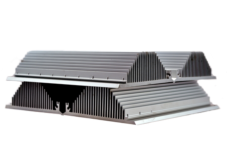
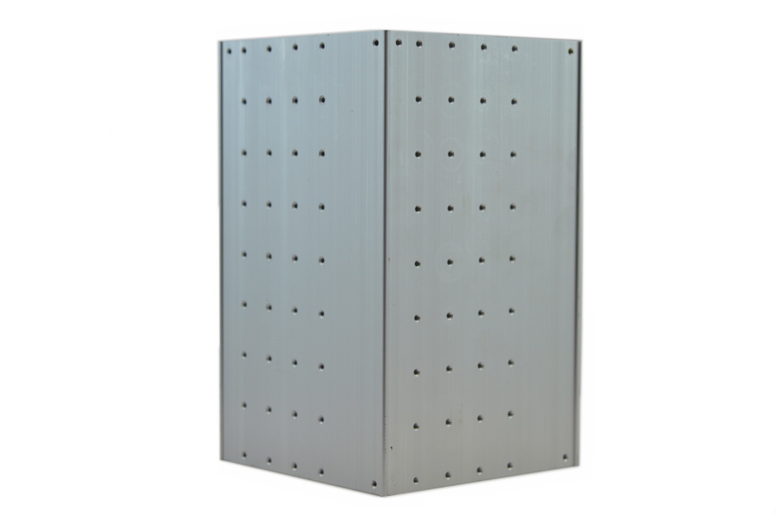
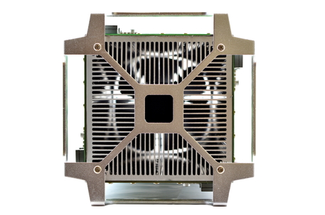
Locate the four heatsink blocks and stand them all upright so the row with 6 screws holes are at the top - this orientation is important! Interlock their corners one at a time to create a closed box, still standing on its end.
Step 2
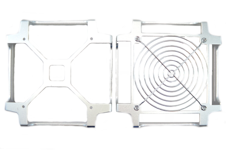
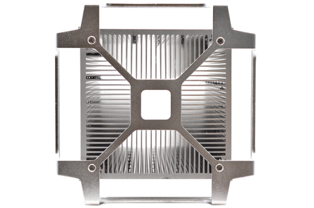
Locate the 'X' shaped stand and the four M4*8 screws - these are the fatter screws kept in a separate bag. Screw the stand into the heatsink blocks to hold them together.
Locate the 'X' shaped stand and the four M4*8 screws - these are the fatter screws kept in a separate bag. Screw the stand into the heatsink blocks to hold them together.
Step 3
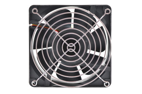
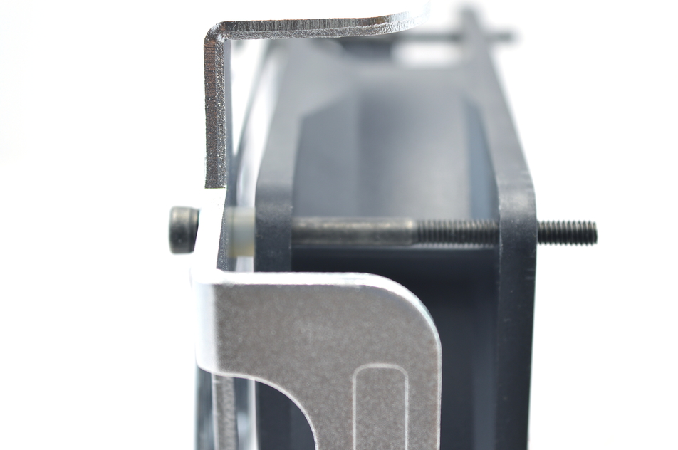
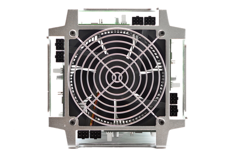
Locate the 'square' shaped stand, the four M4*55 screws, the four plastic washers, the fan and the fan grill. Hold the fan grill over the stand in one hand, and in the other guide the screws through each corner hole. Then, squeezing all the screws to prevent them falling out, place it all on the table. Place the plastic washers onto the screws. Do not forget this step! Place the fan onto the screws, with its supporting frame facing the fan grill. You should have the sandwich as pictured as below.
Locate the 'square' shaped stand, the four M4*55 screws, the four plastic washers, the fan and the fan grill. Hold the fan grill over the stand in one hand, and in the other guide the screws through each corner hole. Then, squeezing all the screws to prevent them falling out, place it all on the table. Place the plastic washers onto the screws. Do not forget this step! Place the fan onto the screws, with its supporting frame facing the fan grill. You should have the sandwich as pictured as below.
Step 4
This is the last fiddly step of the build. Locate the controller and rest the heatsink half down onto it so only only 1-2cm of the controller is exposed. Holding the fan sandwich together, rest it on the final bit of the controller. The fan will want to rotate down from the top edge so keep that edge pinned in. Slowly mate the two surfaces and screw in each of the corners. Be careful to not over-tighten these screws and bend the plastic of the fan. Once completed, you
have the basic structure of the ASICMiner Tube done!
Step 5
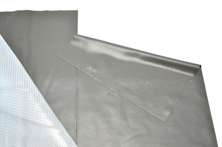
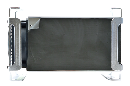
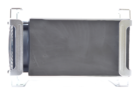
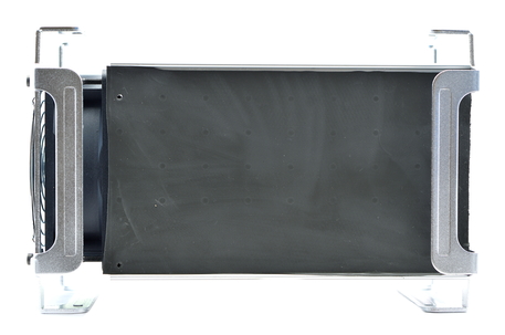
Locate the sheet of thermal compound and peel off a strip. It isn't sticky but it is statically charged and will cling to anything and everything it touches (including dust and dirt). Try and place it as straight as possible the first time, preferably on the top horizontal surface of the Tube. You can place it a few times, and keep picking it to straighten it and to remove bubbles.
Once you're happy with the placement, massage any pockets of air to the outer edges. Peel
back one corner and visually locate one of the screw holes before replacing the the thermal compound and flattening it again. Carefully puncture the compound with a screwdriver - this is to help you line up the board in the next step.
Step 6
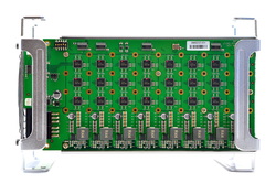
Locate a hashing board. Carefully slide it under the handles into place - connectors facing the fan. If it appears too long immediately STOP and do not force it into place. Check that you have correctly placed the plastic washers between stand and fan or fan and heatsink.
Screw in 3 or four of the corner screws to line up the board, using the aligning holes you made in the step before if required. Locate the bag of M3*6 screws and screw in all the screw holes in the board starting from the centre in a spiral. This action pattern helps remove any air trapped between the board and thermal compound. For speed I would recommend adding all the screws to the hole first, before tightening them.
Step 7
Check and then double check all screws have screws in them and have been tightened. Every screw is required to prevent local overheating. Repeat steps five and six for all 4 hashing boards, rotating the Tube each time so you are always working on the top horizontal surface for ease.
Check and then double check all screws have screws in them and have been tightened. Every screw is required to prevent local overheating. Repeat steps five and six for all 4 hashing boards, rotating the Tube each time so you are always working on the top horizontal surface for ease.
Step 8
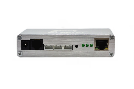
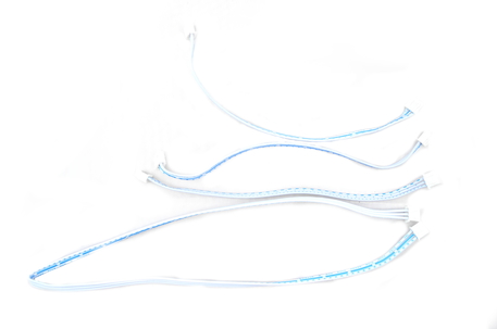
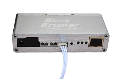
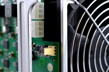
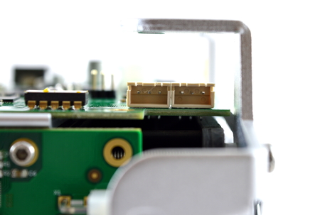
Locate the four data cables. Using the three shorter cables and starting at any board (board A), wire it to the next board (board B). Wire board B to the next board (board C), and wire board C to the next board (board D). From either board A or D, wire the long cable to the controller's port closest to the ethernet port (labelled UART1). Plug the fan into any of the hashing boards.
Locate the four data cables. Using the three shorter cables and starting at any board (board A), wire it to the next board (board B). Wire board B to the next board (board C), and wire board C to the next board (board D). From either board A or D, wire the long cable to the controller's port closest to the ethernet port (labelled UART1). Plug the fan into any of the hashing boards.
Step 9
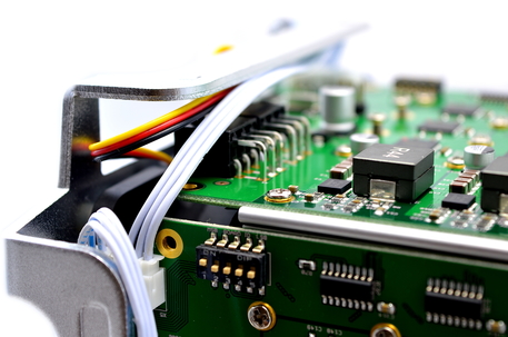
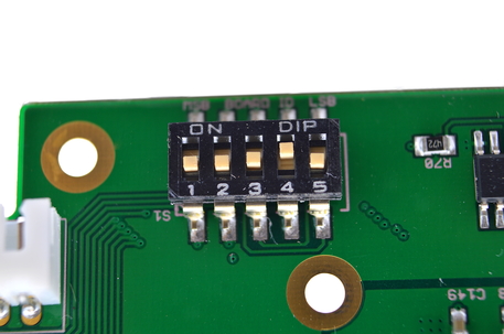
Flip the Tube over and check that all screws are present and screwed in. Make sure that the 5 bit switch on each mining board sharing a controller is unique.
Flip the Tube over and check that all screws are present and screwed in. Make sure that the 5 bit switch on each mining board sharing a controller is unique.
2) Powering
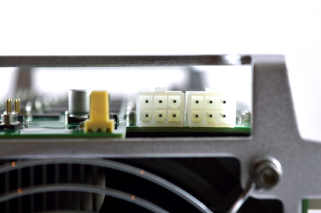
Tubes do not come with a power supply, and you will need a typical computer PSU with 8xPCI-E 6 pin power connectors. Strictly only 4 PCI-E connectors are required at stock speeds, however it will reduce cable temperatures by utilising all 8. I would strongly recommend the PSU above as it has 8 PCI-E cables andthick 16 AWG wiring. While you can power the same miner with multiple power supplies, under no circumstances should you attempt power the same mining board with different power supplies.
We also need to tell the PSU to always be on, as there isn't a motherboard to do this. Cut a paperclip into a U and insert it into the green wire and either black wire to the side of the green wire. Tape it up for safety. The power supply will now be controlled by its switch on the rear socket.
The controller board also requires a 12V 2.5mm barrel connector, 1A minimum.
3) Cooling
A single, high static pressure 120mm fan is used to cool the central aluminium core. Noise levels are reasonable considering the 900W of heat being removed with a single fan. If construction instructions were following correctly, the fan should be in a pull arrangement.
It is noteworthy that the end closest to the fan may become very hot to the touch extremely hot to the touch (including the handles) during operation, so please be careful during handling and maintenance.
|
|
4) Case
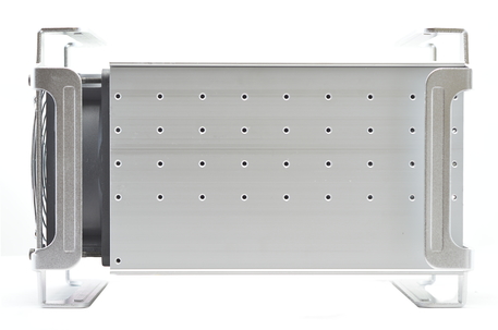
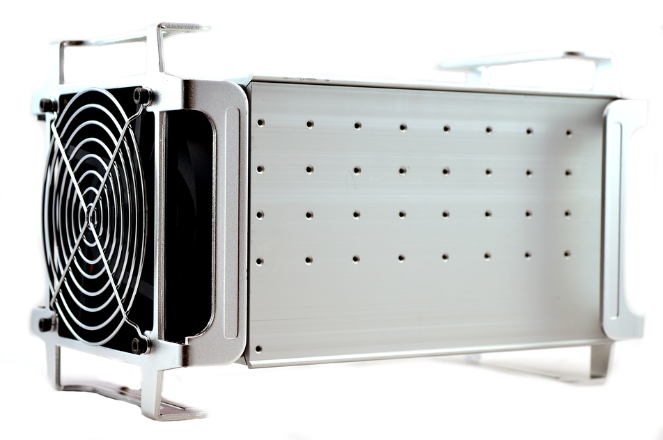
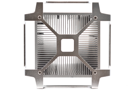
The central aluminium heatsink provides the core of the frame and structure of the miner, and is supplemented by radial feet at either end. Both are constructed of low weight aluminium, giving an overall miner weight of just 6KG for a near 1TH unit. Tubes are stackable both side to side and top to bottom. The addition of a rubber strip between miners would be beneficial to reduce vibration.
The central aluminium heatsink provides the core of the frame and structure of the miner, and is supplemented by radial feet at either end. Both are constructed of low weight aluminium, giving an overall miner weight of just 6KG for a near 1TH unit. Tubes are stackable both side to side and top to bottom. The addition of a rubber strip between miners would be beneficial to reduce vibration.
5a) Configuration
An external 32bit PIC board is used as the controller, and can handle 8 daisy chained Tubes.
Wiring:
Software:
Alternative Subnet Change:
An external 32bit PIC board is used as the controller, and can handle 8 daisy chained Tubes.
Wiring:
- Plug in an ethernet cable from the controller board to you router.
- Plug in the three wired long cable from the miner to the white socket on the controller board closest to the ethernet port.
- Make sure each mining board sharing a controller has a unique 5 bit switch code. See the troubleshooting section for all the codes.
- Plug in all eight PCI-E connectors into the Tube.
- Plug in the 12V barrel connector into the controller board.
Software:
- Power on the power supply using its switch at the back.
- Make sure or your router's subnet is 0, ie 192.168.0.x. If not then change it to 0, this is just temporary. ***If this is not possible, see below***
- Using a browser, navigate to 192.168.0.254:8000 - this goes to the Tube's configuration page.
- Navigate to Settings.
- Change IP to something memorable, and on your preferred subnet.
- Change gateway to the IP of your router.
- Change primary DNS to the IP of your router.
- Change secondary DNS to "8.8.8.8".
- Enter Pool URL in the format as below. Please see below notes on pool selection.
- Enter the port of your pool.
- Enter your miner username and password.
- Set ASIC clock at 270 for stock speeds and 300 for overclocked speeds.
- Click update and restart.
- Navigate back to the IP of the miner you set to check mining started.
- You can then change your router subnet back to whatever you are used to using.
Alternative Subnet Change:
- Unplug your computer from all internet sources.
- Plug in an ethernet cable from the controller to your computer.
- Navigate to Control Panel -> Network and Sharing Centre -> Change Adapter Settings.
- Right click on your ethernet adapter -> Properties.
- Click on "Internet Protocol Version 4" and click properties.
- Select "Use the following IP address" and enter the following:
- IP Address: 192.168.0.1, Subnet Mask: 255.255.255.0, Default Gateway: 192.168.0.254.
- Plug in an ethernet cable from the controller to you router.
- Restart the configuration instructions as above.
5b) Configuration - Using Proxy (Optional)
To use pools outside of the above list, a proxy must be used. These instructions are for BFGMiner on Windows, but the same can be replicated on a Pi or Linux.
To use pools outside of the above list, a proxy must be used. These instructions are for BFGMiner on Windows, but the same can be replicated on a Pi or Linux.
Using BFGMiner:
Optional:
- Download BFGMiner. Extract it to "C:\Program Files (x86)".
- On the computer the proxy is running on, open a command prompt window (run/search and type cmd).
- Enter "ipconfig /all". Scroll down to your computer to find its IP address.
- Using a browser, navigate to the Tube's configuration page.
- Enter the computer's IP address into the "Pool URL" field. Enter "3333" into the "Pool Port" field.
- Username and password fields do not matter (enter x in both). Click Update/Restart.
- Create a .bat file in notepad (by saving it as .bat) and save it on your desktop. Put the following text inside, changing the pool url and miner login as desired.
Optional:
- If you want the proxy to start in the background when you turn your computer on, navigate to Control Panel -> Administrative Tools -> Task Scheduler.
- From the right hand list, select "Create Basic Task". Name it "Start Proxy" and click "Next". Select the trigger "When the computer starts" and click "Next".
- Select "Start a Program" and click "Next". Browse to your desktop and select the .bat we created. Click "Next", select the tick box and click "Finish".
- Select "Run whether user is logged on or not" and tick the check box "Run with highest privileges". Click "Okay".
cd C:\Program Files (x86)\bfgminer-4.7.0-win64
bfgminer -o mint.bitminter.com:3333 -u username_worker -p anypassword --stratum-port 3333 --set-device PXY:diff=512
cd C:\Program Files (x86)\bfgminer-4.7.0-win64
bfgminer -o stratum.btcguild.com:3333 -u username_worker -p anypassword --stratum-port 3333 --set-device PXY:diff=512
cd C:\Program Files (x86)\bfgminer-4.7.0-win64
bfgminer -o us1.ghash.io:3333 -u username_worker -p anypassword --stratum-port 3333 --set-device PXY:diff=512
|
|
6) Troubleshooting
|
Problem
How do I set up more than one miner on one controller? How do I reset settings to default? My power supply's cables are braided or aren't color coded |
Solution
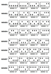
- There is a 5 bit switch on each hashing board which must be configured to be unique in order for the controller to detect it. Set the first miner's boards as "MINER1" in the below diagram, the second's as "MINER2" etc. The long cable from one unit should be plugged into the empty connection on the other to daisy chain the connections on the other. - Hold and press the black push button on the controller board.
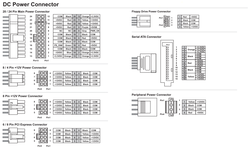
- See below diagram for pin-outs. |
7) Where to buy
General Safety Tips
|
|
|
Legal disclaimer: This information is for general guidance and does not constitute expert advice. We are not responsible if you, your property or a third party is injured or damaged as a result of any interaction with this information, and no warranty is provided. All text and images are covered under copyright law, dogiecoin.com.
|

