Bitmain Antminer C1 Setup Guide
|
Contents
0a) Introduction 0b) What You Need 1) Powering 2a) Cooling 2b) Cooling Assembly 3) Case 4) Configuration 5) Troubleshooting 6) Where to buy |
|
0) Introduction
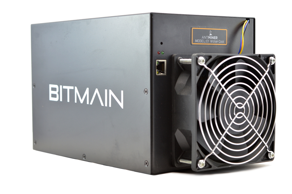
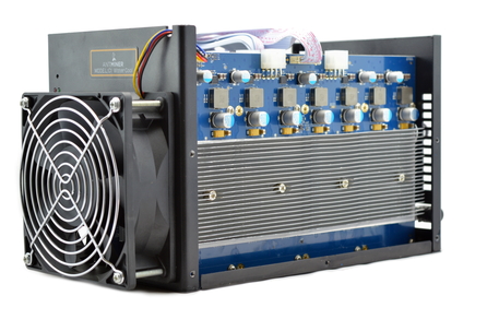
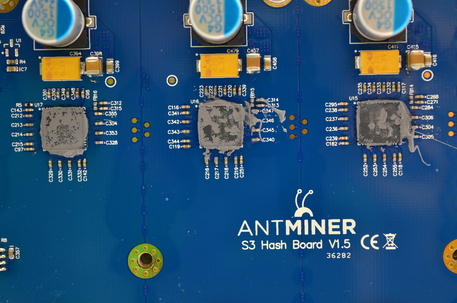
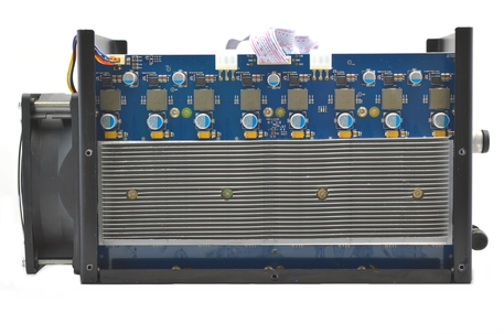
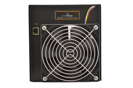
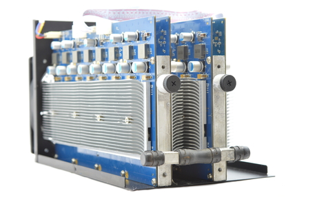
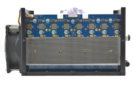
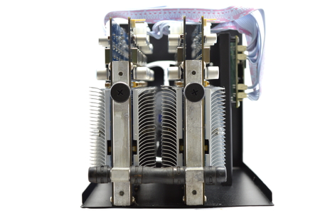
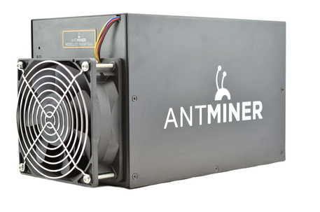
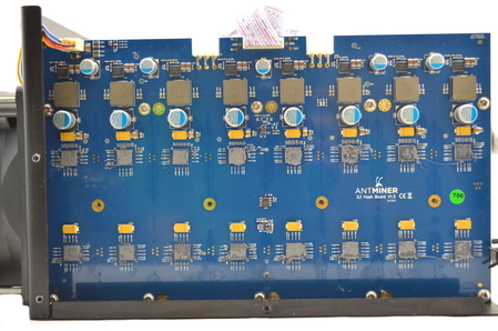
Bitmain's AntMiner C1 combines two Antminer S3's into the same compact case of the S3. This is made possible by the addition of watercooling [purchased separately] which significantly lowers temperatures and noise levels. 64 BM1382 chips are spread across four hashing boards with each waterblock cooling two boards in a sandwich. C1s require assembly but do not require an external controller.
Bitmain's AntMiner C1 combines two Antminer S3's into the same compact case of the S3. This is made possible by the addition of watercooling [purchased separately] which significantly lowers temperatures and noise levels. 64 BM1382 chips are spread across four hashing boards with each waterblock cooling two boards in a sandwich. C1s require assembly but do not require an external controller.
|
Chips
Rated Hash Rate Rated Voltage Rated Current Power Consumption |
- 64x Bitmain BM1382 Gen2
-~1000GH - 12V - 68A - 820W |
0b) What You Need
You will need a few accessories and a power supply to get started. *You will also need the custom C1 watercooling kit from here.
You will need a few accessories and a power supply to get started. *You will also need the custom C1 watercooling kit from here.
Click your flag to find everything* you need to get started at Amazon!
1) Powering
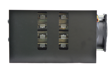
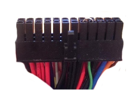
C1's do not come with a power supply, and you will need a typical computer PSU with 8xPCI-E 6 pin power connectors. Strictly only 4 PCI-E connectors are required at stock speeds, however it will reduce cable temperatures by utilising all 8. We also need to tell the PSU to always be on, as there isn't a motherboard to do this. Cut a paperclip into a U and insert it into the green wire and either black wire to the side of the green wire. Tape it up for safety. The power supply
will now be controlled by its switch on the rear socket.
2a) Cooling
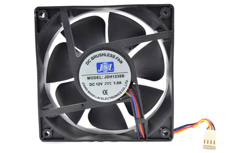
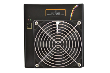
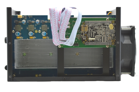
A single, high static pressure 120mm fan is used to cool the central aluminium core. Noise levels are reasonable considering the 900W of heat being removed with a single fan. If construction instructions were following correctly, the fan should be in a pull arrangement.
It is noteworthy that the end closest to the fan may become very hot to the touch extremely hot to the touch (including the handles) during operation, so please be careful during handling and maintenance.
2b) Cooling Assembly
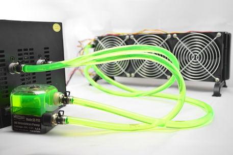
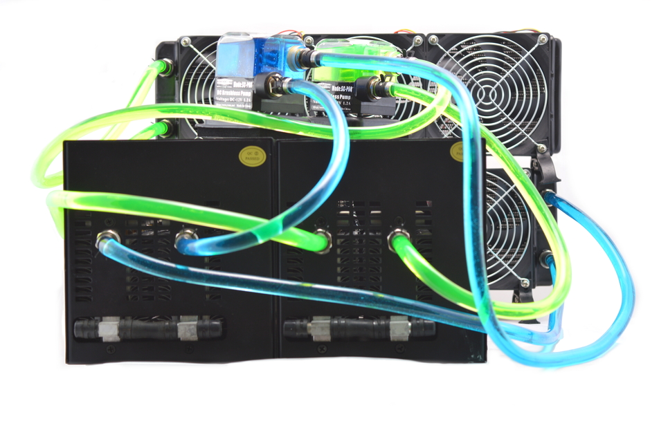
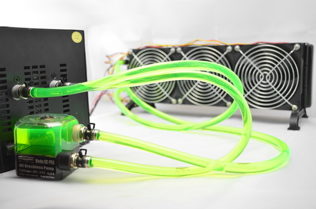
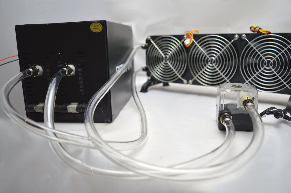
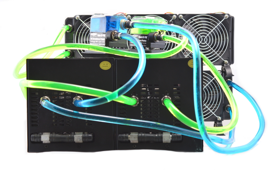
Assembly of the cooling system takes about 20 minutes per miner and consists of 10 major stages. Please make sure you've completed each stage before you move on, and reread the instructions before proceeding to make sure you're not going to damage your Tube. These instructions assume you have purchased the customised $50+$30 kit from here, as well as 1L of watercooling coolant.
Assembly of the cooling system takes about 20 minutes per miner and consists of 10 major stages. Please make sure you've completed each stage before you move on, and reread the instructions before proceeding to make sure you're not going to damage your Tube. These instructions assume you have purchased the customised $50+$30 kit from here, as well as 1L of watercooling coolant.
Step 1
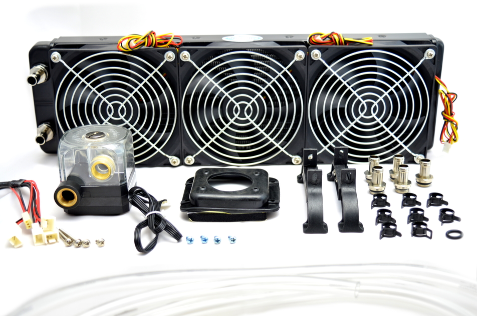
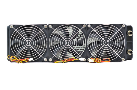
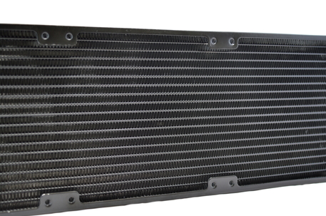
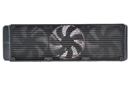
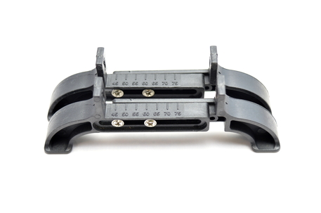
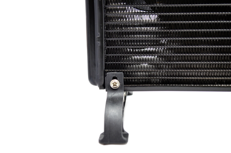
We are going to start by preparing the radiator. This is a high density, 360mm aluminium radiator with three 120mm fans installed already. Locate the two plastic radiator stands, and slide them until the indicator on the top reads ~51mm. Screw the two screws in to hold the 51mm in place, being careful not to damage the plastic threads.
We are going to start by preparing the radiator. This is a high density, 360mm aluminium radiator with three 120mm fans installed already. Locate the two plastic radiator stands, and slide them until the indicator on the top reads ~51mm. Screw the two screws in to hold the 51mm in place, being careful not to damage the plastic threads.
Step 2
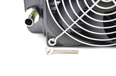
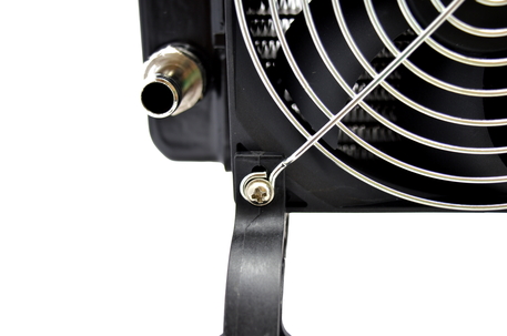
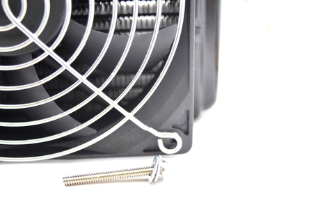
Unscrew the two bottom corner screws on each end fan and discard the washers. Place the radiator stands between the fan grill and radiator on each side. Use the same screws as you removed to screw through the fan grill, radiator stand and into the radiator. Locate the two short, silver screws and screw in the other side of the radiator stand into the radiator.
Unscrew the two bottom corner screws on each end fan and discard the washers. Place the radiator stands between the fan grill and radiator on each side. Use the same screws as you removed to screw through the fan grill, radiator stand and into the radiator. Locate the two short, silver screws and screw in the other side of the radiator stand into the radiator.
Step 3
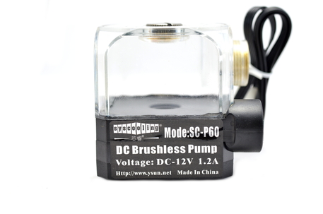
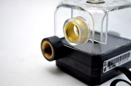
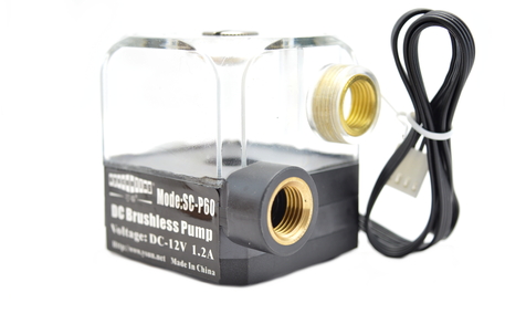
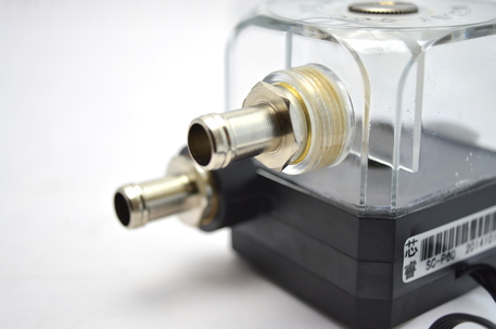
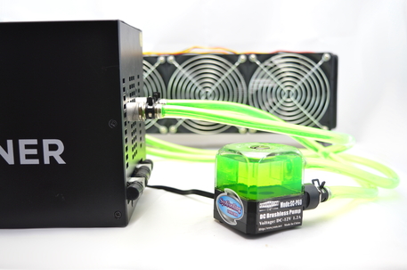
Next we will prepare the pump. This is a 15W pump with 3m of head pressure and 450 litres per hour of flowrate. Locate two fittings and screw them into the brass inserts. You'll need to tighten them slightly more than hand tight to prevent leaks occurring or the tube turning the fittings.
Next we will prepare the pump. This is a 15W pump with 3m of head pressure and 450 litres per hour of flowrate. Locate two fittings and screw them into the brass inserts. You'll need to tighten them slightly more than hand tight to prevent leaks occurring or the tube turning the fittings.
Step 4
Locate the tubing and cut three pieces from it, two of 70cm length and one of 40cm length. You can do this with standard scissors but try and make the ends flat.
Locate the tubing and cut three pieces from it, two of 70cm length and one of 40cm length. You can do this with standard scissors but try and make the ends flat.
Step 5
The C1 is next to be prepared.
There are then various different ways to do the next stage depending on what type of fittings you have.
The C1 is next to be prepared.
- First open the case by unscrewing the 5 screws on each side.
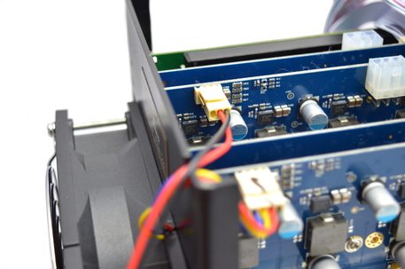
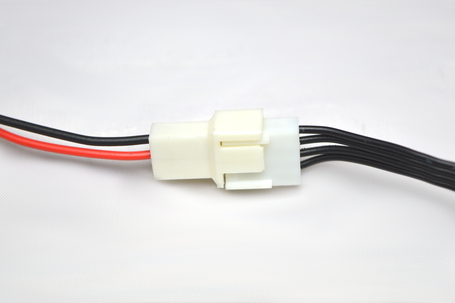
- Locate the cable harness and plug in the 3 pin fan header to the header closest to the end with the fan.
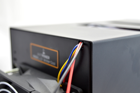
- Place the cable through the nook in the case where the fan's cable lays and replace the case.
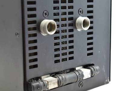
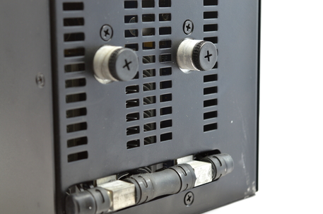
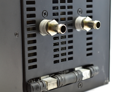
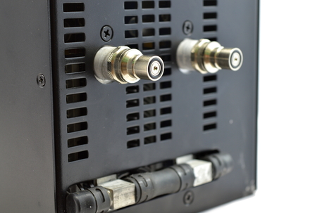
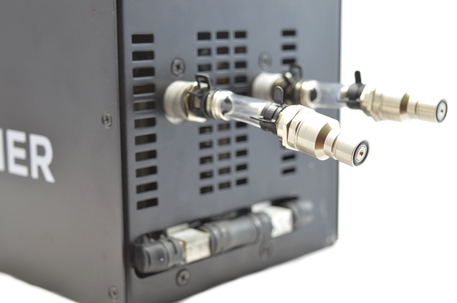
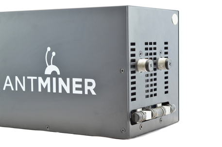
- Unscrew the two black caps from the C1. A small amount of fluid may leak when you unscrew these caps.
There are then various different ways to do the next stage depending on what type of fittings you have.
Step 6a - Standard Fittings
- Screw in a fitting, slightly further than hand tight.
- Place a spring clamp on the 40cm length of tubing, and work it 10cm down the tube so it is out of the way.
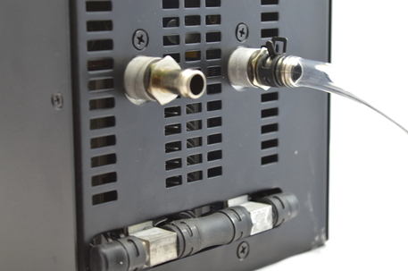
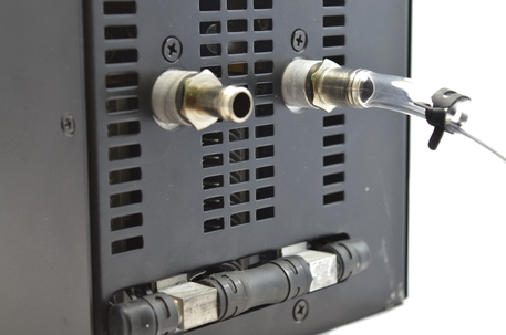
- Then push the tube over the end of the fitting until the tube hits the end of the fitting. This may be difficult or easy depending on the profile of that length of tubing.
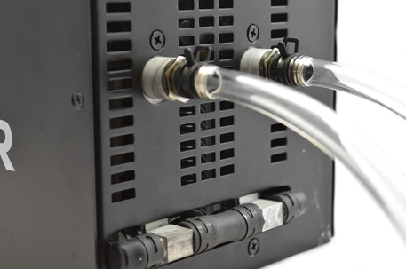
- Slide the spring clamp over the fitting until it is squeezing the tubing over the smooth section of the fittings.
- Repeat for the other side using one of the longer sections of tubing.
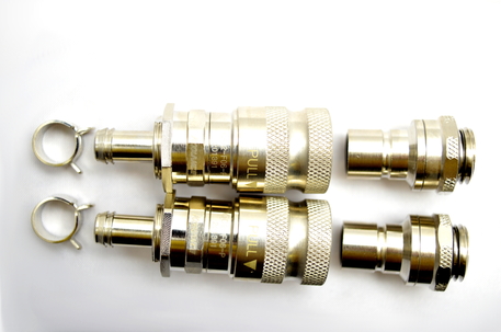
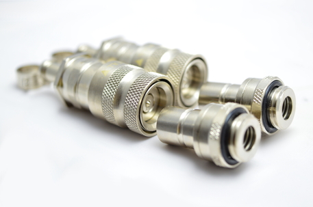
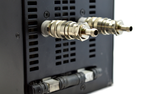
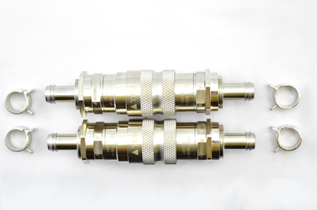
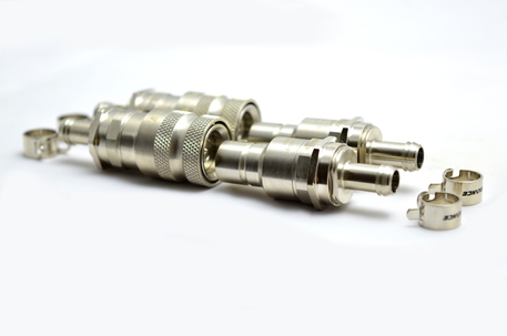
Step 6b - 1/4" BSP Quick Release Fittings
- Screw in the half of the pair which has a thread into the C1's threads, slightly further than hand tight.
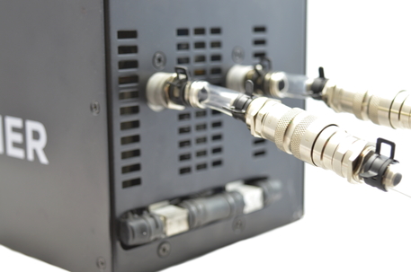
- Join the other half of the quick release connector to mate the pair.
- Place a spring clamp on the 40cm length of tubing, and work it 10cm down the tube so it is out of the way.
- Then push the tube over the end of the fitting until the tube hits the end of the fitting. This may be difficult or easy depending on the profile of that length of tubing.
- Slide the spring clamp over the fitting until it is squeezing the tubing over the smooth section of the fittings.
- Repeat for the other side using one of the longer sections of tubing.
Step 6c - Quick Release Barb Fittings
- Follow Step 6)a above but using two 8cm lengths of tubing instead
- Place a spring clamp over the exposed length of tube and work it down out of the way. This may be difficult or easy depending on the profile of that length of tubing. Slide the spring clamp over the fitting until it is squeezing the tubing over the smooth section of the fittings.
- Push one end of the quick release fitting into the tube.
- Slide the spring clamp over the fitting until it is squeezing the tubing over the smooth section of the fittings.
- Join the other half of the quick release connector to mate the pair.
- Place a spring clamp on the 40cm length of tubing, and work it 10cm down the tube so it is out of the way.
- Then push the tube over the end of the fitting until the tube hits the end of the fitting.
- Slide the spring clamp over the fitting until it is squeezing the tubing over the smooth section of the fittings.
- Repeat for the other side using one of the longer sections of tubing.
Step 7
Connect the short tube from the C1 to the outlet [the bottom, black fitting] on the pump using the process in Step 6)a. Connect the third long tube to the other port on the pump using the process in Step 6)a.
Connect the short tube from the C1 to the outlet [the bottom, black fitting] on the pump using the process in Step 6)a. Connect the third long tube to the other port on the pump using the process in Step 6)a.
Step 8
Connect the long tube coming from the C1 to whichever fitting on the radiator is the lowest. Connect the higher one to the pump. We have now completed the circuit so double check all spring clamps are in place and that the tubing is at or near to the end of the fitting.
Connect the long tube coming from the C1 to whichever fitting on the radiator is the lowest. Connect the higher one to the pump. We have now completed the circuit so double check all spring clamps are in place and that the tubing is at or near to the end of the fitting.
Step 9
Flip the Tube over and check that all screws are present and screwed in. Make sure that the 5 bit switch on each mining board sharing a controller is unique.
Flip the Tube over and check that all screws are present and screwed in. Make sure that the 5 bit switch on each mining board sharing a controller is unique.
Step 10
- Unscrew the cap on the top of the pump and fill it with coolant.
- Lift the pump up so the coolant drains into the tubing.
- Refill the pump and then turn on the PSU (and the pump). You can either quickly keep filling the pump as it flows out (you need to be fast) or keep your finger on the power supply's switch to turn it off when it gets close to empty. Do NOT allow the pump to spin with no fluid in the pump as this will damage it or cause it to fail. Remember the pump takes approximately 3 seconds to stop spinning once the power is removed.
- Continue until there are no more bubbles in the system, and the pump is refilled to full. Turn the radiator upside down once or twice to help remove trapped air.
Step 11 (optional)
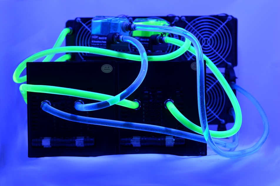
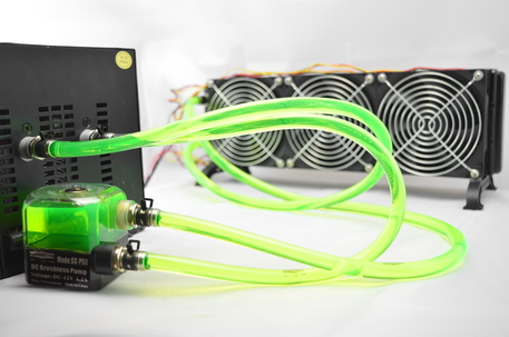
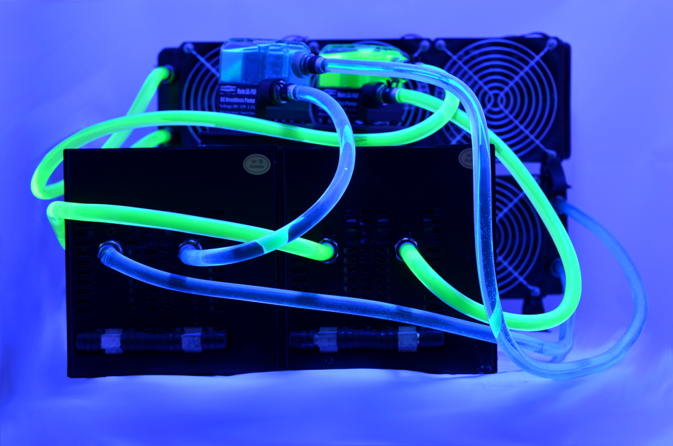
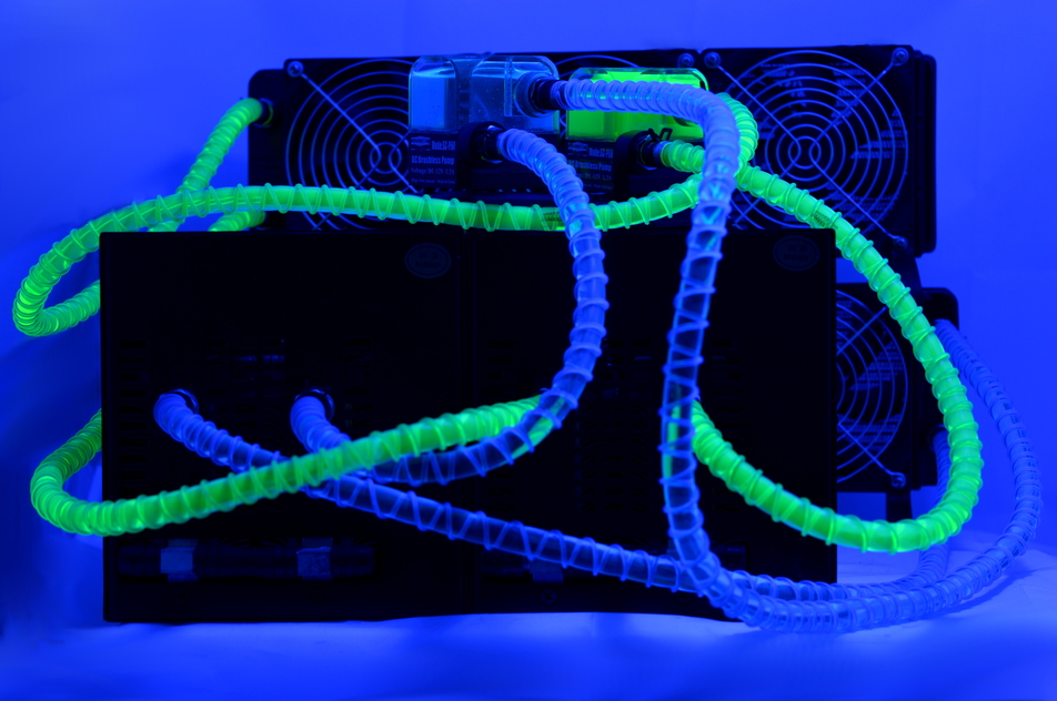
You can also purchase anti kink coils to prevent the tubing from kinking and getting blocked when placed at an angle or being twisted. They also look great under UV light.
You can also purchase anti kink coils to prevent the tubing from kinking and getting blocked when placed at an angle or being twisted. They also look great under UV light.
|
|
3) Case
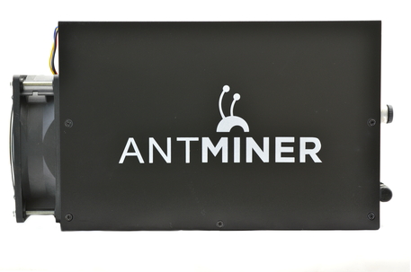
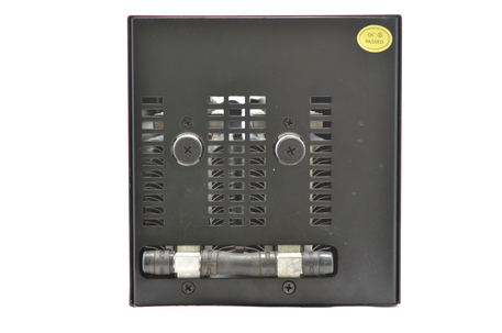
The C1 is entirely enclosed in an extremely strong shroud that is not going to be damaged at all. The internal frame is minimal but solid and well designed. All fans have grills to complete what is possibly the most child and pet friendly miner on the market. C1's are stackable when placed on their side due to the top access required for the PCI-E cables.
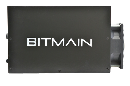
A shipped C1 weighs 6kg and the unit measures 320 mm x 155 mm x 167 mm without watercooling installed.
4) Configuration
The C1 is standalone and does not require an external controller.
Wiring:
Configuration:
Alternative Subnet Change:
The C1 is standalone and does not require an external controller.
Wiring:
- Prepare the paperclip for the PSU's 24 pin connector.
- Prepare the watercooling for the miner.
- Plug in the eight PCI-E cables to the miner.
- Plug in an ethernet cable from the AntMiner to you router.
Configuration:
- Power on the power supply using its switch at the back.
- Make sure that your router's subnet is 1, ie 192.168.1.x. If not then change it to 1, this is just temporary. ***If this is not possible, see below***
- Using a browser, navigate to 192.168.1.99 - this goes to the C1's configuration page.
- Login using "root" as both the username and password.
- Navigate to Network -> Interfaces -> WAN -> Edit.
- Change protocol to DHCP and click "Save & Apply".
- Using a browser, navigate to your router and find the IP it has assigned the C1 and navigate to that IP.
- Navigate to the page Status -> Miner Configuration. Enter your pool information in the below format.
- Select "Beeper ringing" to "false" and click "Save & Apply".
- Navigate to the page "Miner Status" to check mining has started.
- You can then change your router subnet back to whatever you are used to using.
Alternative Subnet Change:
- Unplug your computer from all internet sources.
- Plug in an ethernet cable from the AntMiner to your computer.
- Navigate to Control Panel -> Network and Sharing Centre -> Change Adapter Settings.
- Right click on your ethernet adapter -> Properties.
- Click on "Internet Protocol Version 4" and click properties.
- Select "Use the following IP address" and enter the following:
- IP Address: 192.168.1.1, Subnet Mask: 255.255.255.0, Default Gateway: 192.168.1.99.
- Plug in an ethernet cable from the AntMiner to you router.
- Restart the configuration instructions as above.
Servers : stratum+tcp://stratum.btcguild.com:3333
User : username_worker
Password: anypassword
Servers : stratum+tcp://us1.ghash.io:3333
User : username.worker - auto creates workers!
Password: anypassword
Servers : stratum+tcp://stratum.mining.eligius.st:3334
User : payoutbitcoinaddress
Password: anypassword
|
|
5) Troubleshooting
|
Problem
"x" in a row on miner configuration page Almost all "x" on one row of "Chips" How do I change the login password? What is the SSH login? Can I turn the beeping off when the miner stops mining? I can connect to the AntMiner but its not hashing? What temperatures should I aim for? Where can I get the latest firmware? How can I tell what firmware version I have now? How do I install the latest firmware? How do I reset settings to default? My power supply's cables are braided or aren't color coded! |
Solution
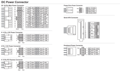
- There is a faulty chip - nothing we can do. Hash rate will be affected by ~1.5%. - A hashing board may be mispowered or faulty. Recheck your cabling and PSU. - Navigate to System -> Administration. Enter the current password and enter your new one twice. - Username is "root", password is "root". - Navigate to Miner configuration and turn "Beeper Ringing" to false. - Set the protocol to DHCP via Navigate to Network -> Interfaces -> WAN -> Edit. If you don't want to use DHCP, navigate to Network -> Settings and make sure "Gateway" is set to the IP of your router. - Try and achieve <50 for best hash rates, and <60 for long lifetimes. Temperatures should not be let to rise above 70C. - Download from Bitmain's site. - Navigate to System -> Overview and look at "File System Version". - Download firmware as above. Navigate to System -> Upgrade and click "browse". Select the downloaded file and click "Flash image". Do NOT interrupt this process or you will brick the unit. - Use a paperclip to press the reset button - located next to the ethernet connector - down for 5-10 seconds. The miner will then reset with stock settings. - See below diagram for pin-outs. |
6) Where to buy
General Safety Tips
|
|
|
Legal disclaimer: This information is for general guidance and does not constitute expert advice. We are not responsible if you, your property or a third party is injured or damaged as a result of any interaction with this information, and no warranty is provided. All text and images are covered under copyright law, dogiecoin.com.
|

